Detail design drawings span carriage way. Typical inlet detail drawing no.

Details Of Slab Reinforcement And Beam Framing Plan Dwg File How To Plan Reinforcement Beams
9 inch wall 8 inch base flat top slab xmanhole base to be constructed of class a concrete minimum of 12 inches placed under flow line of pipe xheight of bench to be 08 x.

. Sum e clear 10 date. DETAIL DRAWINGS RASTRA is a stay-in-place insulated concrete form that is structurally strong energy-efficient soundproof resistant to fire high wind mold and rodents and is made from 85 recycled materials. CONCRETE SLAB DISCLAIMER.
Always refer additional notes provided in the drawings. Two-Way Concrete Floor Slab with Beams Design and Detailing. Fe415 Clear cover.
The diameter of bar generally used in slabs are. 315-20 PART C-FIGURES AND TABLES Fig. No framing or structural members are to be modified notched or cut without the approval of the engineer.
Culvert Extension - A portion of a culvert built beyond the limits of a previously existing culvert. ¾Detailing involves thecommunication of the engineers design to the contractors who build the structure. Isometic section frame const w-slab floorpdf.
124 ScalesThe scales used should be indicated on all structural drawings preferably under the title of each view. X 18 in edge beam dimensions 14 in. Drawings showing the size and location of the reinforcement in a concrete structure.
Concrete Slab Reinforcement Deformed Welded Wire. Monolithic Slab on Gradedwg. Concrete Slab Reinforcement Deformed Welded Wire - Double Mat.
X 27 in interior beam. Fill Height - The vertical distance from the top of the top slab of a. Drawing list revision date drawing no.
3-Typical details for one-way joist construction pg. 2-Typical details for beams pg. The imposed loading on the floor is 5 KNm2 and an allowance of 25KNm2 for finishes etc.
TRUSS OR RAFTER CONNECTION 2 - 5 REBAR GRADE 60 MONOLITHIC. Design the slab system shown in Figure 1 for an intermediate floor where the story height 12 ft column cross- sectional dimensions 18 in. Thickness of the slab is decided based on span to depth ratio specified in IS456-2000.
Foundation with perimeter Drainage Systemdwg. 7 inch wall 8 inch base flat top slab 8 ft id. Dia round pipe in table of quantities riprap at rcp outlets filter fabric dia.
Top of footing slab rl 98706 bottom of pcc slab rl 97606 bearing level rl 103706 bearing level rl 103706 bottom of pcc slab rl 102606 existing road level. AASHTO Type II Prestressed Concrete Girder. M20 Type of steel.
L-Typical details for one-way solid slabs pg. 6 inch wall 8 inch base flat top slab 6 ft id. Properties of flat slab.
The maximum diameter of bar used in slab should not exceed 18 of the total thickness of slab. Slab detail drawing pdf MATERIAL Link DISCLOSURE. 5 inch wall 6 inch base flat top slab 5 ft id.
Consisting of a bottom slab two wall elements and a top slab. Two-Way Concrete Floor Slab with Beams Design and Detailing. Foundation with perimeter Drainage Systempdf.
Fcu 40 KNm2 fy 460KNm2. Minimum reinforcement is 012 for HYSD bars and 015 for mild steel bars. Flat slab on and larger mhs all joints shall be made watertight using all weather butyl gasket e-z stik or approved equal on inside and.
123 Direction An arrow indicating the direction of North should be placed on every drawing that contains a plan view. 6 mm 8 mm 10 mm 12mm and 16mm. Isometic section frame const w-slab floordwg.
This PDF file contains a chapter of 23 pages with various aspects of flat slabs including four example of flat slab design. These structural details dwg AutoCAD drawing download for concrete beam and slab system will help you to do any slab reinforcement detail drawing. Perimeter Drainage- High Waterdwg.
AASHTO Type II Prestressed Concrete Girder. T able of c ontents c hapter 1 m asonry c avity w all d etails s hear c onnected c hapter 2 m asonry c avity w all d etails a djustable t ies c hapter 3 b rick v eneered s teed s tud b ackup w all d etails s hear c onnected c hapter 4 b rick v eneered s teel s tud b ackup w all d etails s lotted t ies c hapter 5 s ingle w ythe l oadbearing m asonry w all d etails c hapter 6 m. The slab is without drops and is supported internally and on the external long sides by square columns.
The PDF covers the following topics. Maximum spacing of main bar is. You should think this website has an affiliate romantic relationship andor another content link to your individuals or enterprises talked about in or connected to from this page and will obtain commissions from buys you make on subsequent Internet sites.
Designer - Individuals designated by the Structural Engineer to use this manual to design and detail culverts. The direct design method. Drawing list revisions 123-sets s110 structural cover sheet sheet nosheet title sheet total symbols and abbreviations for concrete as per aci general existing construction north 1 sd package - 03-30-11 5 symbol legend structural abbreviations s210 foundation plan s501 foundation details s502 steel details s220 roof framing plan dd.
Or span flared end section section b-b. 4-Standard fabricating tolerances for bar sizes 3 through ll pg. Unless otherwise indicated details shown are to be considered typical for similar conditions.
It involves the translation of a good structural design from the computer or calculation pad into the. Foundation Detail wwwdouglascous 100 Third Street Castle Rock Colorado 80104 3036607497 Fax 3034797271 9292014 12 6 MINIMUM 18 MINIMUM BELOW GRADE ½ ANCHOR BOLTS A MINIMUM OF 7 INTO CONCRETE WITHIN 12 OF PLATE SPLICES AND 6 MAXIMUM SPACING. 2 DETAILS AND DETAILING Chapter 8-Referenc es pg.
CEMCO assumes no liability for failure resulting from the use of its drawings computations or for failure resulting from the use of alternate materials or improper application or installation. Monolithic Slab on Gradepdf. Name signature as sheet a3 size nts gb-dl-01.
Connect NCDOT Resources Structures Standard Drawings 2018 English Stds. This drawing is supplied solely to assist in the selection and application of CEMCO products. Prepare a detailed structural drawing of one way continuous slab for a hall of clear dimensions 7m wide and 1177 m long use following data Centre to centre distance of supporting beams 30 m Span of the beams 723m Beams are supported on walls of 023 m thickness Cs of beam 230 x 450 mm Grade of concrete.
Flat Slab Design PDF 2. Placing drawings are in Part B addressed to the detailer. Slab Detail Drawing Pdf.
The ownner shall familiarize themselves with the drawings. Determination of bending moment and shear force. Concrete Slab Reinforcement Deformed Steel Double Mat.
Two Way Slab Reinforcement Details in English Unit Concrete Slab. A floor slab in a building where stability is provided by shear walls in one direction N-S. All these two-way slab reinforcement details dwg will be used in any concrete beam slab floor system.
Standard Drawings Standard specification drawing files in DGN and PDF formats.
B Designed Slab Reinforcement Details Download Scientific Diagram

Two Way Slab Reinforcement Details Reinforced Concrete Concrete Slab Structural Drawing

Roof Slab Drawing Pdf Pdf Architectural Elements Concrete
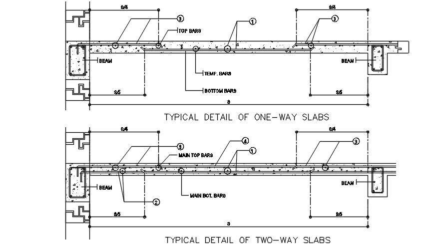
Typical Detail Of Two Way Slab Drawing Provided In This Autocad File Download This 2d Autocad Drawing File Cadbull

One Way Slab Reinforcement Details Structural Design Engineer Concrete Design Reinforcement

Reinforcement Detailing Of Reinforced Concrete Slabs The Constructor

Typical Slab Reinforcement Structure Design Detail Autocad Dwg Plan N Design

Reinforcement Detail Of Floor Slab Dwg Drawing Thousands Of Free Autocad Drawings
0 comments
Post a Comment