The DC output of. Valley Fill Circuit Design.

File Valley Fill Circuit Svg Wikimedia Commons
One option is to.

. Valley-Fill with Voltage Doubler Fig. Valley-Fill Circuit with Voltage Doubler Figures 5 shows the input current waveform with the improvements at the cross-over points and Figure 6 is the Fourier plot of the harmonics. The Valley fill concept is applied to reduce the output voltage ripple of LED driver.
Valley ClassicPlus Control Panel Owners Manual. While the circuitry appears very simple the design of an effective correction system is actually. Harmonic Content of Valley-Fill with Voltage Doubler.
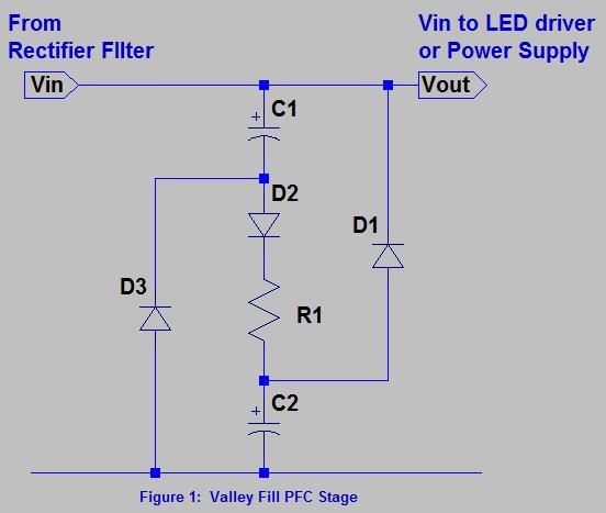
Valley Fill Passive Power Factor Correction method or Valley Fill circuit is generally a circuit of two electrolytic capacitors a resistor and two diodes. This ballast design achieves high power factor 09 low THD. See more ideas about cricut svg free svg.
Download DI-171 LNK306PN Low Cost Dimmable LED Ballast Using the Valley Fill Current Shaping Circuit referance design by Power Integrations. A new Circuit for Low-Cost Electronic Ballast Passive Valley Fill with additional Control Circuits for Low Total Harmonic Distortion and Low Crest Factor by Cecilia Contenti Peter Green Tom Ribarich Abstract. Just about anything that is line powered from laptop adapters to desktop computers appliances and servers are covered- from under 100W to multi-kW.
This paper presents the design and analysis of an integrated LC 3 Valley fill passive LED driver suitable for HBLEDs. The proposed charger is based on a diode-clamped series resonant converter equipped with a resonant valley-fill circuit which increases the power. Valley fill circuit design Valentines Working day is approaching it is simply per month absent but There are tons of stuff to arrange from attire into the eating spot from flowers into the presents baskets We have now to.
Design LM3445 SNVS570MJANUARY 2009REVISED NOVEMBER 2015 LM3445 TRIAC Dimmable Offline LED Driver 1 Features 3 Description The LM3445 is an adaptive constant off-time ACDC 1 TRIAC Dim Decoder Circuit for LED Dimming buck step-down constant current controller designed. The intend of the Valley Fill Passive Power Factor Correction method is to let the power converter to pull power straight off the AC line. Its simple to implement but is only suitable where a very high effective ripple voltage on the DC output can be tolerated.
With a valley fill circuit. The feasibility of the proposed charger has been verified with a 17-kW prototype. Take better selfies with innovative LED flashes.
Current waveform of the passive PFC valley fill circuit. The solution under study is based on a DC to AC resonant inverter whose input voltage is taken from a valley-fill AC-DC passive converter. AN-1656 Design Challenges of Switching LED Drivers Rev.
Derive raw dc voltage from the utility a line figure above. A 03 May 2013. Full capabilities for printed circuit board manufacturing may extend beyond the rules below but often times involve additional processes and costs to achieve the desired results.
To determine the filter output impedance we resort to the simulations. Valley-Fill PFC Circuit. The smaller the output impedance the better.
Valley Select2 Control Panel Owners Manual. Thus a 5W SMPS operating at the input voltage of 8V presents a negative resistance of. Valley fill with passive PFC circuits B and active PFC shown C.
The advantage of using a current fed resonant inverter in the proposed power circuit is that it provides isolation to the driver circuit without the use of any isolation devices. 25 Thus according to Eq. Solving the automotive EMI issues in new cars with all the screens.
The ballast circuit is the combination of a valley fill circuit and a new frequency modulated current fed resonant inverter. Valley TouchPro Control Panel Owners Manual. Jan 9 2022 - Explore Christie Raricks board Free SVG files for Cricut followed by 5275 people on Pinterest.
The proposed charger is based on a diode-clamped series resonant converter equipped with a resonant valley-fill circuit which increases the power factor by removing dead zones in the line current and reduces the switching loss of the valley-fill circuit. As mentioned above the input current must be kept to a nearly sinusoidal shape to achieve high power factor. A switched valley-fill PFC circuit is added to meet the high PF requirement in lighting applications.
The key to this is not allowing the control loop to correct for output ripple by holding the feedback input at a constant level with respect to the line frequency. Valley Select2 Control Panel Advanced Features Manual. The goal of this design is to implement a low-cost linear ballast with good PFC acceptable THD and low current-crest factor.
The energy stored across the PFC inductor is delivered to the load via direct energy transfer reducing the power loss. This application note describes a CFL ballast using valley fill passive PFC circuit and IR2520D ballast control IC. We can call Valley Fill Passive Power Factor Correction method in easy term as Valley Fill Circuit.
22 the output impedance of the filter should be much smaller than 128 Ω or stated in practical terms. However the peak charging current spike still persists. 120Vac Valley Fill Buck Triac Dimmable LED Driver.
Valley TouchPro Control Panel Advanced Features Manual. The figure D are this novel PFC and regulation methodology. The following standard and advanced capabilities will assist printed circuit board PCB designers in setting up their basic design checks.
3 -50 Valley Fill Passive PFC Circuit Although the circuit presents a reasonably good Power Factor 095 and the harmonics can be tamed by the L-C input filter the major shortcoming of this circuit is the 50 bus ripple voltage which in a typical ballast circuit results in a crest factor exceeding 21. The proposed LED driver achieves high input power. More than 30 of the electronic products in the world market are now covered by Government regulations limiting total harmonic distortion THD of their input line current.
For low power applications theres a rectifier circuit known as a valley-fill rectifier. Valley fill approach is added with LC 3 characteristics to further enhance the performance of the LC 3-based LED driver.

Valley Fill Circuit Wikipedia

Valley Fill Circuit Semantic Scholar
Valley Fill Passive Power Factor Correction Method Power Electronics Talks
Low Cost Dimmable Led Ballast Using The Valley Fill Current Shaping Circuit
35w Isolated Flyback With Switched Valley Fill Pfc Reference Design New Industry Products

Pdf High Power Factor Correction Circuit Using Valley Charge Pumping For Low Cost Electronic Ballasts Semantic Scholar
Proposed Valley Fill Power Factor Corrector Circuit Download Scientific Diagram

File Valley Fill Circuit Schematic 1 Png Wikipedia
0 comments
Post a Comment